Here's how I took my stock Bandit headlights out and installed a set of Hella™ 90mm low and high beam modules. They produce superior light to the stock modules, and they should not be succeptible to the black dust that rendered the stock lighting almost useless. The low beam is wide and even, and the high really lights up the world. I was able to retain the use of the stock adjuster plates, so fine tuning of the beam will be as described in the owners manual.
The Hella link is here (myhellalights.com) and the store where I bought them is here (rallylights.com, high-beam, low-beam). My total cost was about $160 including the lights and plugs, wire, rtv silicone, rivets, bolts/washers/nuts, nylon bushings and electrical tape. Total time was around six hours, but I admit I wasn't clocking myself.
Parts ordered:
- HL68136 90mm High Beam Lamp, H9 Bulb, Adjusters, each $58.75
- HL68137 90mm Low Beam Lamp, H9 Bulb, Adjusters, each $58.75
- HL87193 H9 Connector with terminals and seals, each $6.70 (x2)
Parts purchased at the hardware store or aquired elsewhere:
- #8/32x1 bolts, nylon insert nuts, washers (x12)
- #8 x 3/8" nylon bushings (x8)
- 18 guage or heavier wire, 12" lengths (x2)
- milk jug caps (x2)
- rtv sealant (or silicone caulk)
- pop rivets
- electrical solder
- glass cleaner and paper towels
Tools used:
- Suzuki stock toolkit
- kitchen range
- tape measure
- 10mm socket or wrench
- #2 phillips screwdriver
- drill and drill bit index
- Dremel™ rotary tool and abrasive cutoff wheel
- Sharpie™ markers
- Exacto™ or utility knife
- bench vice
- wire stripper
- soldering iron
As with any instructions, I suggest you read through these before you begin. If anything isn't clear, or if I have any errors, please
click on images for a larger view
Adendum: Here's a great set of photos on Flickr that may help.
1. Remove the headlight housing. I followed Blade's windscreen replacement how-to (no longer free, CD available) and my Clymer manual. I won't go into that process here since it's been covered well by these two sources. Really, it's all pretty straight forward, but Blade's page helps prevent damage to several delicate fairing pieces.
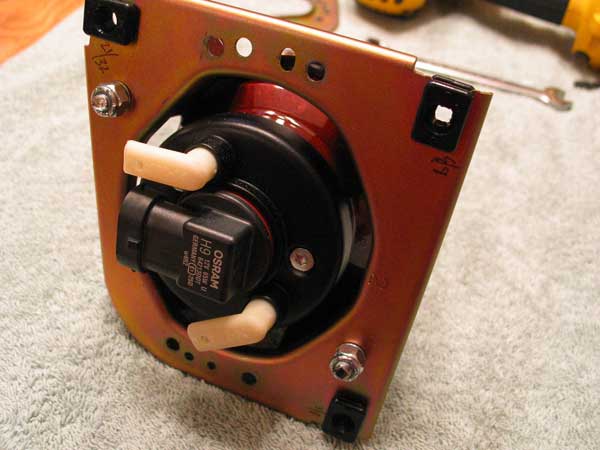
 2. Set your kitchen timer for 10 minutes and heat the housing in an oven on its lowest bake setting. This shouldn't be more than about 150 degrees F. Begin checking the temperature of the housing after about 10 minutes. **DO NOT OVERHEAT THE HOUSING AND DO NOT FORGET IT'S IN THE OVEN!** Once the plastic body of the housing feels warm, the non-curing sealant Suzuki used to connect the two halves of the housing will be soft enough to pull apart. Gently pry the locking tabs open and pry the halves apart. Take care to avoid slips which could damage the finish on the inside of the housing. A sharp knife can be used to slice the sealant once separation has begun. Try to keep the sealant fairly smooth to make the seal tight later. This photo shows the front of the housing removed, along with the trim ring, light blocker, and lense from the low beam module.
 3. Before removing the stock adjustment plates, measure the protrusion of each adjuster screw and write it on the plate. A fine point Sharpie works well. This will allow you to get a ballpark alignment on installation of the new modules.
 Remove the mounting plates by backing out the three 10mm bolts on the back of the housing for each plate. Do this in several steps to avoid damaging the plastic adjuster nuts with extreme angles.
 Remove the four #2 phillips screws in each plate to remove the plates from the stock headlight modules. At first glance, the two plates seem identical. Actually, they have a reversal in the stamping direction of the inner flange. I chose to reverse the mounting plates since it worked better with the new Hella high beam module. Lay one plate face down, and one face up, with the same orientation. Transfer the adjuster screw measurements to the other plate, matching the locations. Do the same for the other plate. Cross out the old measurements (or use a different color pen) to avoid confusion.
 4. First, we'll mount the high beam module (hbm) to the adjuster plate. Using what was the low beam mounting plate, lay the hbm over the center flange with the 'top' marking on the hbm aligned with the top of the plate. As you can see, it almost centers itself on the flange.
 Using #8/32x1 bolts, nylon insert nuts, and a 3/16" drill bit, mount the hbm to the plate. Keep the top ears on the hbm parallel with the top of the adjuster plate. Take care when drilling, since the hbm housing is cast magnesium, and therefore is quite hard. Drill carefully to avoid cracking the housing. Alignment in the Bandit's light housing is critical, so be patient when making the holes in this step. Look the project over frequently and make careful marks. Do not overtighten the nuts.
 For clearance of the adjuster screws, the outer portion of the hbm's ears must be cut away. I used a Dremel and a cutoff wheel. It's only necessary to remove portions of the three ears that correspond to the adjuster screws. Ease the edges of the cuts to avoid injury later.
 You may now reinstall the plate and hbm into the headlight housing. Using the measurements taken previously, set the plate to the stock location. Again, use several steps to avoid damaging the adjusters.
 5. We'll now mount the low beam module (lbm). Since its housing is wider and longer than the hbm's housing, we'll need to segment the adjuster plate and use it in three pieces. First, draw a circle, centered on the plate opening, with a diameter of 4-1/8 inches. Take care to position this accurately. I cut a cardboard template to mark the shape of the lbm's ears and tabs on the adjuster plate. Shown here are the resulting marks. I removed the plastic inserts to avoid damage while cutting. You may find this unnecessary.
 I used the Dremel and cutoff wheel to cut out the corners of the plate outside the lbm outline. Again, ease the edges to avoid injury. Here you can see the three pieces mounted in their original positions. Only draw the plate fragments onto the adjuster screws far enough to align them with each other.
 In order to clear the sides of the mounting ears on the lbm, and to properly set the depth of the lbm relative to the headlight housing, I've used 3/8" long nylon bushings, sized for the #8 bolts. As you can see here, the bushings are installed in between the adjuster plate and the lbm mounting ears. Using a bushing as a guide, and with the bushing located as far outward as possible, drill two holes into each of the three ears that correspond with the mounting plate fragments. Remove the ends of the ears, as with the hbm, to clear the adjuster screws.
 Examine the hbm and notice how the right side of the module lines up with the adjuster screws. Try and make sure the lbm aligns the same way. Carefully position the lbm over the three plate fragments and mark the centers of the holes in the lbm. Drill the plates to accept #8 bolts. Mount the plates to the lbm using the nylon bushings, bolts, and insert nuts. Again, alignment is critical, so be patient here.
 Thread the lbm onto the adjuster screws in several steps using the measurements taken earlier. When that's done, look over the project and check for snugness of all parts.
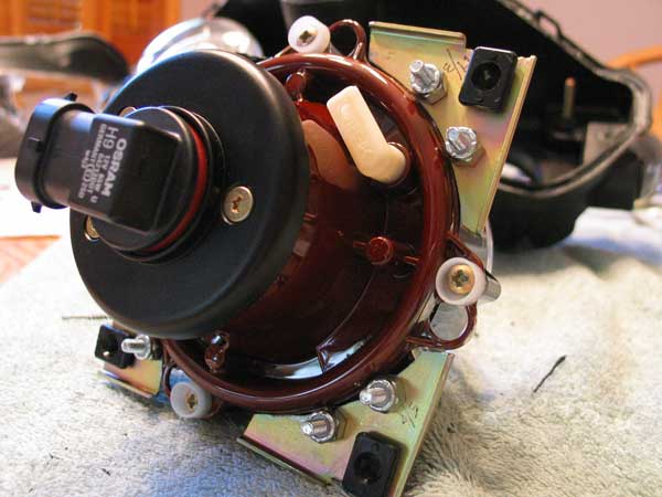
 As you can see, the hbm is much shorter than stock, while the lbm approximates the length of the stock module.
 6. Now follow the supplied instructions to install the H9 bulb plugs onto two 1' lengths of wire. I used sheathed 16 guage two strand wire. Later we'll need to cut off the old plugs in the fairing and solder or crimp the wires together. This will add needed length to accomodate the changed positions of the bulb connections. Also carve an opening into the rear of the low beam housing to clear the plug. I used a Dremel and an abrasive barrel.
At this point, carefully clean both the exposed inner surfaces of the headlight housing (you can remove the chromed portion with the four phillips screws) and the back half where the new modules mount. Then wipe the new headlight lenses. I used a soft cloth misted with window cleaner. Remember that these will no longer be accessible after the next step.
Test fit the halves of the housing to see that the new modules are properly aligned. If all looks good, reheat the housing, as in step 2, and press the halves together. Work all the locking tabs back into position. Let the housing cool.
 7. In order to prevent dust from entering the housing, we'll need to seal the rear openings. I found that a milk jug cap fit nicely in the stock dust cover, and used rivets and rtv sealant to attach it in the hole.
 Drill a small hole for the supply wire to come through on the high beam side. Make sure the modified dust cap is in place before soldering the wires together later in the project.
I used a similar procedure on the low beam side, but I used some rtv to keep the inner portion of the dust cover extended outward to clear the new bulb base.
Carefully cut away the rubber until the plug fits through the dust cover. This cover doesn't need to be in place before soldering, since the plug fits through the opening.
8. Reinstall the headlight housing on your Bandit. Solder or crimp the wires together in the fairing. The black/white wires are ground, but I didn't find any indication that there's a hot/ground order with the new plugs. Either way should work.
9. Reinstall the fairing. Adjust the beam patterns to your taste using the stock method. If your new Hella modules come into contact with the headlight housing, turn the three adjuster screws clockwise an equal distance to back the module away without losing its aim.
10. In the old motorcycle modders' tradition, pop a cold one. You've earned it.


Update: Bazza (or Baz or Barry or Zukeman, depending on where you meet him) did some fantastic research into the deficiency of the Bandit's stock headlight wiring. I've ordered a relay kit from Eastern Beaver to remedy this based on his suggestions. Read more about his results and see the comparison photos at his site. I expect that when I'm done I'll have the type of lighting I want for after-hours riding. Sweet.
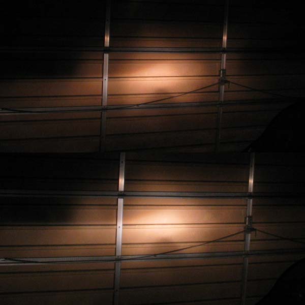
Update: Here are photos taken before and after the relay install, with the engine off. The improvement is obvious, but I suspect it will be compounded with the engine running.

TESTIMONIALS from those who have done the Rowdy Mod (as of October 2006, five other people have attempted this mod):
"jimsiggy" at Maximum-Suzuki says, "I did the mod a few weeks ago, and finally took it out after dark last night (more than just a cruise around the neighborhood). The real improvement is on the low beam, the high beam is better too but the stock HB was not lacking like the stock LB did." Read more here (you must be registered at Maximum-Suzuki).
"Baz" said at his site, "I found that the Hella units put out a far superior light, due to better focusing" and "Believe me folks, I tried my best to not go through with the Hella mod because of the work, but after much playing around, I do feel it is probably the best permanent solution to the Bandit light dilemma." His site is here.
"Micklevanon" from Sport-Touring.net says, "...Hella 90mm headlight modules, and a new wiring harness with relays. Pain in the ass to do, especially the low beam, but it's done. Photos are on my Flickr site.
"I went out last night to aim them, and am amazed at the amount of light they put out. I can actually see now."
Follow